- Acknowledgements
- Introduction
- Chapter 1: Measurement Tools, Layout & Job Planning
- Chapter 2: Basic Hand Tools
- Chapter 3: Filing & Sawing
- Chapter 4: Grinding, Reaming, Broaching & Lapping
- Chapter 5: Drills & Drilling Operations
- Chapter 6: Threads & Threading
- Chapter 7: Turning Operations
- Chapter 8: Milling Operations
- Chapter 9: Fastening Methods
- Chapter 10: Why Steel Hardens
- Chapter 11: Safety & Good Shop Practices
- Chapter 12: Other Shop Know-how
- Appendix I: Sharpening Steel Lathe Tools
- Appendix II: Surface Speed Table & Cutting Tool Selector Chart
- Appendix III: Decimal Equivalents of Fractional, Letter & Metric Drills
- Glossary
- Index
Chapter 10
Machine Shop Steel Metallurgy
Success is simply a matter of luck. Ask any failure.
—Earl Wilson
Introduction
The hardening and softening of metals using heat is essential to making the tools and products of the modern world, from kitchen knives to jet engine blades. Because steel is the most common material heat-treated, as well as the most often used metal in the machine shop, this chapter focuses on steel.
Metallurgy and heat-treatment is a complex subject. Metallurgists, physicists, and heat-treat specialists often spend a lifetime in its study, so it is not possible to completely cover the subject in this chapter. For critical or complex applications, professional guidance and equipment are essential. However, there are several important heat-treating tasks that can be done in the machine shop with limited equipment, and we will cover these tasks.
This chapter looks at the crystalline structure of metals and explains why steel can be hardened using heat. It reviews practical aspects of heating, quenching, tempering, and annealing steel. The equipment needed to perform these processes, and their advantages and limitations are explained, as are common heat-treatment problems and their solutions. Several types of tool steels, which the machinist can readily heat-treat, are detailed. In addition, the uses and differences between drill rod, drill blanks, and reamer stock are discussed, along with their common alloys.
There are other uses for heat in the shop too: annealing work-hardened copper and brass, softening metals to bend them, soldering and brazing, and expanding parts prior to slipping them over other parts. These operations are easily done and offer practical solutions and alternatives to the machinist.
There is also an explanation of metal fatigue and the steps to avoid it.
Section I – Metals Made from Iron
Engineering Materials
The element iron makes up all but a few percent of the contents of iron-based metals. These metals have very different properties depending on their carbon content. Table 10–1 lists the iron-based metals, their carbon content, characteristics, and applications.
|
Material |
Percent Carbon |
Characteristics & Applications |
|
Wrought Iron |
< 0.008 |
Very soft material. |
|
Low-carbon |
< 0.30 |
Also called mild steel or machine steel. Does not contain enough carbon to be hardened, but can be case hardened. Used for parts, which do not need to be hardened, like nuts, bolts, washers, sheet steel, and shafts. Also used in structural steel and machine tool frames. |
|
Medium-carbon Steel |
0.30–0.60 |
May be hardened. Used where greater tensile strength than low-carbon steel is needed. Used for tools like hammers, wrenches, and screwdrivers, which are drop-forged and then hardened. |
|
High-carbon Steel |
0.60–1.7 |
May be hardened. Also known as tool steel. Used for cutting tools, punches, taps, dies, reamers, and drills. |
|
High-speed |
0.85–1.5 |
Hardenable. Used for lathe and milling machine cutting tools and drill bits. Retains hardness and cutting edge at red heat. This is the least costly member of the HSS family. See Table 10-2 for details on the alloying elements of all the HSS alloys. |
|
Cast Iron |
> 2.1 |
Cannot be hardened, but available in several forms with differing properties. |
Table 10–1. Carbon content of major iron-containing metals.
HSS Steel Alloy |
Percent |
|||||
|
Carbon |
Chromium |
Tungsten |
Molybdenum |
Vanadium |
Cobalt |
|
|
M2 |
0.85 |
4.00 |
6.00 |
5.00 |
2.00 |
— |
|
M42 |
1.10 |
3.75 |
1.50 |
9.50 |
1.15 |
8.00 |
|
T1 |
0.75 |
4.00 |
18.00 |
— |
1.00 |
— |
|
T15 |
1.50 |
4.00 |
12.00 |
— |
5.00 |
5.00 |
Table 10–2. Principal alloying elements of high-speed steels.
Section II – Why Steel Hardens
Structure of Metals
What is the difference between the structure of metals when molten and solid?
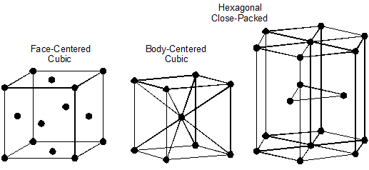
During the hot liquid state metals have no particular structure. There is no orderly, defined, or regular organization among their atoms. However, at lower temperatures, the atoms have less energy, move less rapidly, and atomic forces tend to arrange them into particular structures or patterns called crystals. All metals and alloys are crystalline solids. Figure 10–1 shows the three most common crystal structures in metals and alloys.

Figure 10–1. The three most common crystal structures in metals and alloys.
Behavior of Pure Iron
What behavior does pure iron exhibit as its temperature is gradually raised from room temperature and before it becomes a liquid?
Iron changes its crystalline structure as its temperature increases while remaining solid:
From room temperature to 1670°F (910°C), it is body-centered cubic.
From 1670°F (910°C) to 2535°F (1390°C), it is face-centered cubic.
From 2535°F to its melting point of 2800°F (1538°C), it is again body-centered cubic.
What makes these changes important to us?
These changes between different crystalline structures for pure iron are not particularly important by themselves. However, if we add as little as one percent carbon by weight to iron, we make the iron-carbon alloy called steel. Because of the changes in iron’s crystalline structure at different temperatures, an entirely new series of microstructures form. These microstructures not only have radically different physical properties from pure iron and from each other, but they can be modified by heating and cooling cycles.
Iron-Carbon Diagram
What are these new iron-carbon structures and when are they formed?
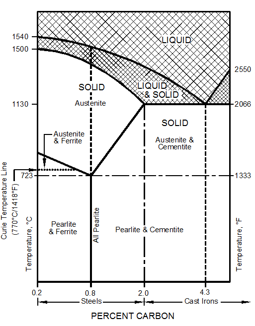
The best way to visualize the interaction of these two elements and the resulting microstructures they form is to study the iron-carbon diagram. This diagram shows the microstructures that exist for a small percentage of carbon in iron at various temperatures, Figure 10–2.
Looking at this diagram, we can see that:
- Steel exists for iron-carbon alloys with between 0.2 and 2 percent carbon.
- Iron-carbon mixtures with more than 2 percent carbon are called cast iron.
- Before the iron-carbon alloy becomes a liquid, there are six different microstructures represented by areas on the diagram:
- Pearlite and ferrite
- All pearlite
- Pearlite and cementite
- Austenite and ferrite
- All austenite
- Austenite and cementite
- In the areas showing two microstructures simultaneously, the structure changes from all one microstructure, to a mixture of the two, to all the other components as we move along the bottom axis, which represents the carbon content. For example, in the “pearlite and ferrite” area of the diagram (bottom left), the structure goes from all ferrite at 0.2 percent carbon, to a mixture of ferrite and pearlite, to all pearlite at 2 percent carbon. This means that in the areas of two microstructures, both the microstructure and its properties change with changes in its carbon content.
- Austenite exists only at a temperature of 1333ºF (723ºC) or higher and can contain up to 2 percent carbon.
Figure 10–2. Iron-carbon diagram.


