- Acknowledgements
- Introduction
- Chapter 1: Measurement Tools, Layout & Job Planning
- Chapter 2: Basic Hand Tools
- Chapter 3: Filing & Sawing
- Chapter 4: Grinding, Reaming, Broaching & Lapping
- Chapter 5: Drills & Drilling Operations
- Chapter 6: Threads & Threading
- Chapter 7: Turning Operations
- Chapter 8: Milling Operations
- Chapter 9: Fastening Methods
- Chapter 10: Why Steel Hardens
- Chapter 11: Safety & Good Shop Practices
- Chapter 12: Other Shop Know-how
- Appendix I: Sharpening Steel Lathe Tools
- Appendix II: Surface Speed Table & Cutting Tool Selector Chart
- Appendix III: Decimal Equivalents of Fractional, Letter & Metric Drills
- Glossary
- Index
Chapter 1
Measurement Tools, Layout & Job Planning
Where observation is concerned chance favors the prepared mind.
—Louis Pasteur
Introduction
Fewer than twenty-five different tools are required to perform basic machine shop layout and measurement. Many of the hundreds of other tools are merely special-purpose versions of these that speed, simplify, or improve the accuracy of a particular task. We will examine these basic twenty-five, see what they do, and how to use them. Each machinist will add more tools to these based on his specific needs.
We will also cover the use of digital slide calipers, which for many jobs are easier and faster than traditional vernier calipers, and their cousins, inside and outside calipers. Toolmakers’ buttons and gage blocks, common to high-precision work, are also presented.
We will then look at layout methods, and finally, we will present work planning rules. Although these rules are not universally valid, they can often prevent problems.
Section I – Basic Measurement Tools
Measuring & Marking Tools for Layout
What are the essential measuring and marking tools and how are they used?
- Layout fluid puts a deep-blue background on the workpiece so scribed layout lines and punch marks stand out sharp and clear. It is applied to clean, dry metal from a brush or spray can and dries quickly. Remove it by wiping it off with denatured alcohol or acetone on a rag. Tip: Using a blue felt-tip marker which is transparent instead of layout fluid is often more convenient when a small area or single point must be scribed. Using layout fluid minimizes the depth needed to make scribe lines visible, which is very desirable because scribe marks are a source of fatigue failure on parts subject to cyclic loads and vibration.
- Scribers, Figure 1–1, apply scratch marks to work indicating the position of holes, openings, and cut lines. Good scribers have hardened and finely tapered points so they can get close to the rule or straightedge, minimizing errors. The last 0.030 inches (0.8 mm) of the scriber should be sharpened to a 60º point by spinning it rapidly in a lathe and tapering it with a flat oilstone. Premium scribers have carbide points. To protect scriber points from becoming blunted, reverse them in their holder or store them inside a drilled-out dowel.

Figure 1–1. Starrett scribers: No. 70 is available with a steel or carbide point which
stores reversed in its handle (top) and No. 67 with a steel point (bottom).
- Straight edges are useful for scribing straight lines and testing surfaces for flatness. They can also be positioned and clamped in place (Vise-Grip® welding clamps work well for this) then used as a guide for cutting with a utility knife. This method is useful in precision cutting of cardboard, gasket materials, and foils. Clamped straight edges also work well for scoring deep lines on acrylic sheet goods so they can be snapped along the score line, somewhat like glass. Because rulers could be damaged when used as cutting guides, straight edges are preferred for cutting. Use an oilstone to remove small nicks. Straight edges may be reground if damaged. See Figure 1–2.

Figure 1–2. Stainless steel straight edge.
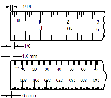
- Steel rules, Figure 1–3, have many uses and are a shop essential. They can be used to measure distances directly on work, to set dividers or surface gages, or as straight edges. There are dozens of sizes and styles from 1 to 144 inches and from 150 to 1000 mm. Precision rules are steel or stainless steel, not aluminum. Their edges are ground, not punched. Because they are machine-divided, not photo-engraved or silk-screened, the tips of dividers can be felt dropping into their scribed division lines. Tip: When using a rule for accurate measurements, the eye can read better by measuring between two lines rather than from the end of the rule to a line.

Figure 1–3. Inch and metric steel rules.
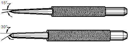
- Prick punches and center punches, Figure 1–4, are needed for fine layout work. Use the prick punch to locate the exact point on the work and strike it with a hammer. If the point is located at the junction of two scribe marks, the prick punch can be used to feel their crossing point. Now that the point has been marked, use the center punch to enlarge and deepen it. The larger punch mark gives the drill a better start. Both punches must be reground when their points dull. Their points can be sharpened by holding the punches tangent to the grinding wheel and rotating them to apply a new cone-shaped point. Sharpening them this way puts the sharpening scratches from the grinding wheel parallel to the punching action. Holding the punch parallel with the axis of the motor shaft puts the grinding scratches at right angles to punching action and reduces punch depth.

Figure 1–4. Prick punch (top) and center punch (bottom).

