- Preface
- Acknowledgements
- Chapter 1: Welding Overview
- Chapter 2: Safety
- Chapter 3: Terms, Joints, & Edge Preparation
- Chapter 4: Tools & Welding Tables
- Chapter 5: Shielded Metal Arc Welding
- Chapter 6: Wire Feed Welding
- Chapter 7: Gas Tungsten Arc Welding
- Chapter 8: Oxyacetylene
- Chapter 9: Controlling Distortion
- Chapter 10: Cutting Processes
- Chapter 11: Brazing & Soldering
- Chapter 12: Common Problems & Solutions
- Chapter 13: Design Tips
- Chapter 14: Fabrication & Repair Tips
- Chapter 15: Tools & Tooling
- Chapter 16: Pipe & Tubing
- Chapter 17: Metallurgy
- Chapter 18: Power Supplies & Electrical Safety
- Chapter 19: Bending & Straightening
- Index
- Credits
Chapter 19
Bending & Straightening
Experience is the name everyone gives to their mistakes.
—Oscar Wilde
Section I – Bending Equipment Overview
Bending is used in almost every fabricated metal product. Because many times welding cannot be done until the bending operations are complete, the welder is often required to perform bending tasks as part of his job.
Sheet metal and thin plate are bent cold, and often thicker plates are bent cold, but thick rolled plates and rolled sections are frequently heated in ovens, with torches or with induction heaters to reduce the bending forces. Table 19-1 shows common steel products and the methods used to bend them.
|
|
Sheet Metal >3/16" Thick |
Plate [3/16"Thick |
Rods |
Shapes: Ts, Ls, Cs & |
Wire |
Pipe & Tube |
|
Hand Bender |
= |
– |
– |
– |
– |
– |
|
Pin Fixtures and Bending Jigs |
– |
– |
=p |
– |
= |
=p |
|
Sheet Metal Brakes |
= |
– |
– |
– |
– |
– |
|
Press Brakes |
= |
= |
= |
– |
– |
– |
|
Roll Brakes |
– |
= |
– |
– |
– |
– |
|
Bending Machines Rotary Mandrel Sand Filling |
=
|
=
|
=p
|
=p
|
=
|
= = |
|
Wrinkle Bending |
– |
– |
– |
– |
– |
p |
|
Rolls |
= |
= |
=p |
=p |
– |
=p |
|
Flame Bending |
– |
p |
– |
p |
– |
p |
|
Line Heating |
– |
p |
– |
– |
– |
– |
|
Flame Straightening |
– |
p |
p |
p |
– |
p |
|
Flame Panel Shrinking |
– |
p |
– |
– |
– |
– |
= : No heat p : Heat used
Table 19-1. Bending methods matched to common steel products.
There are many different styles of bending machines. Here are some of the most common:
- Sheet metal brakes come in a variety of sizes from tabletop, hand-powered units to freestanding, hydraulically actuated models. They work by clamping the sheet metal in place, then, using a hinged section of the brake, force is applied at the point of the desired bend. Most of these brakes are limited to 16-gauge steel. See Figure 19-1.
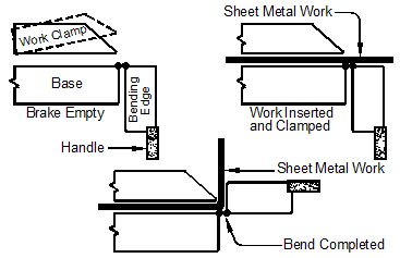
Figure 19-1. Sheet metal brake edge view.
- Press brakes are used to bend heavier gauge sheet metal and all thicknesses of plate. Most brakes are hydraulic, but some use an electric motor-driven flywheel. Much higher forces are needed to bend thicker metal and because of this, press brakes use a mating die design instead of the hinged designs of sheet metal brakes. See Figure 19-2 (left). Medium capacity press brakes have 25–100 ton capacities. Shipyards use even larger press brakes with 2,000-ton ratings.
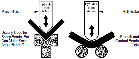
Figure 19-2. Press brake uses matching dies to form sharp bends (left),roll brakes use cylinders or sections of cylinders to form smooth curves (right).
- Roll brakes use steel cylinders, or sections of cylinders, to form long-radius bends in thick steel plate for ship hulls. See Figure 19-2 (right). Roll brakes apply a series of gentle parallel bends to form plate into an arc with constantly changing radii, but they cannot apply compound bends.
Typical Brakes
Figure 19-3 shows an inexpensive vise-insert brake suitable for thin steel and aluminum up to 1/16" by 1" wide, excellent for making small brackets. Figure 19-4 (left) shows a 50-ton hydraulic press that can bend steel and aluminum up to 5/8" thick by 12" wide. Figure 19-4 (right) shows a shop-made hydraulic brake based on a 30-ton bottle jack. The insert shows the male and female bending dies for this brake.
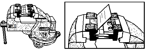
Figure 19-3. A small sheet metal brake used with a vise, suitable for thin sheet metal, aluminum and brass.
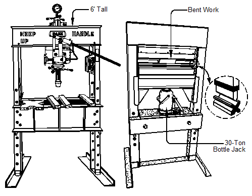
Figure 19-4. Both the commercial hydraulic press (left) and the shop-made hydraulic press based on a bottle jack (right), use steel bending dies (see insert on right).
Section II – Bending Machine Applications
Bending Machine Overview
Bending machines come in dozens of sizes and designs. The smallest are hand- or air-powered and the largest are hydraulic. The principles of these bending machines are basically the same, only the scale and source of bending force differs. The Di-Acro Model 1A, in Figure 19-5, is a small, high quality hand-operated bender that forms round, flat, and square steel, copper, and aluminum stock. With the appropriate dies both tubing and rolled sections can be bent as well.
When bending rolled shapes, pipe, and tubing, the forming dies must fit the work tightly. If the work is not supported and prevented from moving during the bending operations, results will be poor.
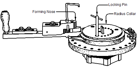
Figure 19-5. Di-Acro bender Model 1A.
Cross-shaped or X-shaped extrusions that cannot be supported and confined by bending dies can be bent by casting the work inside a rectangle of a low temperature metal alloy like CerroBend which melts at 158ºF. The rectangle with the work inside it is bent with tooling for a rectangular bar, and the low-temperature melting alloy is removed in a hot water bath. The low-melt alloy can be reused indefinitely. See Figure 19-6.
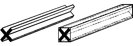
Figure 19-6. Extrusion to be bent (left), and extrusion cast inside a low-temperature alloy to support the X-shaped part during bending (right).
Figures 19-7 through 19-14 show how to use Di-Acro benders to bend a variety of shapes. Most bending machines use the same principals and only differ in force and scale.
Bending Circles
Circles can easily be formed with benders, but spring back must be taken into consideration. Most materials spring back slightly after being bent. To compensate for this, use a radius collar with a smaller diameter than the required circle. Because spring back varies with different materials, actual finished size of the circle is best determined by experiment. Materials should be precut to exact length before forming circles. See Figure 19-7.
