- Preface
- Acknowledgements
- Chapter 1: Welding Overview
- Chapter 2: Safety
- Chapter 3: Terms, Joints, & Edge Preparation
- Chapter 4: Tools & Welding Tables
- Chapter 5: Shielded Metal Arc Welding
- Chapter 6: Wire Feed Welding
- Chapter 7: Gas Tungsten Arc Welding
- Chapter 8: Oxyacetylene
- Chapter 9: Controlling Distortion
- Chapter 10: Cutting Processes
- Chapter 11: Brazing & Soldering
- Chapter 12: Common Problems & Solutions
- Chapter 13: Design Tips
- Chapter 14: Fabrication & Repair Tips
- Chapter 15: Tools & Tooling
- Chapter 16: Pipe & Tubing
- Chapter 17: Metallurgy
- Chapter 18: Power Supplies & Electrical Safety
- Chapter 19: Bending & Straightening
- Index
- Credits
Chapter 16
Pipe & Tubing
In theory there is no difference between theory and practice. But in practice, there is.
—Yogi Berra
Pipe vs. Tubing
The terms pipe and tube are often thought of as interchangeable, but they are not. Pipe usually has much thicker walls than tubing, and these thicker walls allow pipe to accept threads and still have enough metal remaining to provide adequate wall strength to handle fluids under pressure. Tubing, because it has thinner walls, cannot be threaded.
Another difference is that pipe from 1/8–12" diameter is specified by its Nominal Pipe Size (NPS) based on a Standardized Outside Diameter (OD) and by its Schedule, which specifies its wall thickness.
In the 1920s, when the American Standards Association standardized this sizing system, the OD was chosen as a baseline so that pipe with a standard OD—and a wall thickness typical of that time—would have an Inside Diameter (ID) approximately equal to the nominal pipe size (NPS). Today, though, there is no relationship between existing wall thicknesses, ODs, and nominal pipe sizes. However—just to confuse everyone—these nominal sizes and standard ODs remain in use as the “Standard.” Because of this odd system, exact pipe dimensions must be determined from tables.
Since all pipes of the same NPS have the same OD, they all accept the same size threaded fittings regardless of their wall thickness. For a given NPS, the OD stays fixed and the wall thickness varies with increasing schedule numbers. As a result, the ID for a given NPS decreases with the increasing schedule size because the wall thickness of the pipe takes up more room. In general, the larger the schedule number, the higher the pressure the pipe can withstand. There are more than a dozen schedule numbers, although not all schedules are available in all pipe sizes. The most commonly used wall thickness is Schedule 40.
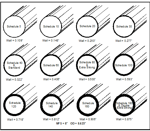
Pipe schedule numbers do not indicate pressure capacity because each NPS of the same schedule has a different wall thickness. The schedule must be calculated on the wall thickness for the particular pressure and application. Now, to confuse everyone even more, the terms Standard (Std.), Extra-Strong (E.S.), and Double Extra-Strong (D.E.S.) are used to describe wall thickness. Figure 16-1 and Table 16-1 show how these terms fit in with pipe schedules.
Tubing wall thickness is specified in inches or Manufacturer’s Sheet Metal Gauge. Generally, decimal inches or Sheet Metal Gauge numbers are used for square or rectangular steel tubing for structural or mechanical applications. Decimal inches are also used for round steel and stainless steel tubing designed for fluid transport. Round tubing is usually stocked in outside diameter increments of 1/16 inch.
There are more than a dozen different thickness gauge schemes (or tables) listed in engineering handbooks. Some are obsolete, some are not used in the U.S., some apply only to ferrous or only to non-ferrous metals, and others only apply to wire diameter. As you can see, there are many opportunities for confusion. If in doubt which table to use, specify pipe wall thickness in decimal inches.

Figure 16-1. Pipe wall thickness comparisons based on schedule number.
Note that all these pipes have the same OD of 8.625 inches, but varying ID with its schedule.
Standard Pipe Sizes
Table 16-1 compares the nominal and actual OD.
|
Standard Pipe Sizes |
||||||||||||||
NOMINAL |
Actual O.D. |
PIPE SCHEDULES WALL THICKNESS |
||||||||||||
|
NPS (inches) |
DN (mm) |
5 |
10 |
20 |
30 |
40 & Std |
60 |
80 & E.S. |
100 |
120 |
140 |
160 |
180 & D.E.S. |
|
|
1/8 |
6 |
.405 |
.035 |
.049 |
|
|
.068 |
|
.095 |
|
|
|
|
|
|
1/4 |
8 |
.540 |
.049 |
.065 |
|
|
.088 |
|
.119 |
|
|
|
|
|
|
3/8 |
10 |
.675 |
.049 |
.065 |
|
|
.091 |
|
.126 |
|
|
|
|
|
|
1/2 |
15 |
.840 |
.065 |
.083 |
|
|
.109 |
|
.147 |
|
|
|
.187 |
.294 |
|
3/4 |
20 |
1.050 |
.065 |
.083 |
|
|
.113 |
|
.154 |
|
|
|
.218 |
.308 |
|
1 |
25 |
1.315 |
.065 |
.109 |
|
|
.133 |
|
.179 |
|
|
|
.250 |
.358 |
|
11/4 |
32 |
1.660 |
.065 |
.109 |
|
|
.140 |
|
.191 |
|
|
|
.250 |
.382 |
|
11/2 |
40 |
1.900 |
.065 |
.109 |
|
|
.145 |
|
.200 |
|
|
|
.281 |
.400 |
|
2 |
50 |
2.375 |
.065 |
.109 |
|
|
.154 |
|
.218 |
|
|
|
.343 |
.436 |
|
21/2 |
65 |
2.875 |
.083 |
.120 |
|
|
.203 |
|
.276 |
|
|
|
.375 |
.552 |
|
3 |
80 |
3.500 |
.083 |
.120 |
|
|
.216 |
|
.300 |
|
|
|
.437 |
.600 |
|
31/2 |
90 |
4.000 |
.083 |
.120 |
|
|
.226 |
|
.318 |
|
|
|
|
.636 |
|
4 |
100 |
4.500 |
.083 |
.120 |
|
|
.237 |
.281 |
.337 |
|
.437 |
|
.531 |
.674 |
|
41/2 |
115 |
5.000 |
|
|
|
|
.247 |
|
.355 |
|
|
|
|
.710 |
|
5 |
125 |
5.563 |
.109 |
.134 |
|
|
.258 |
|
.375 |
|
.500 |
|
.625 |
.750 |
|
6 |
150 |
6.625 |
.109 |
.134 |
|
|
.280 |
|
.432 |
|
.562 |
|
.718 |
.864 |
|
7 |
|
7.625 |
|
|
|
|
.301 |
|
.500 |
|
|
|
|
.875 |
|
8 |
200 |
8.625 |
.109 |
.148 |
.250 |
.277 |
.322 |
.406 |
.500 |
.593 |
.718 |
.812 |
.906 |
.875 |
|
9 |
|
9.625 |
|
|
|
|
.342 |
|
.500 |
|
|
|
|
|
|
10 |
250 |
10.750 |
.134 |
.165 |
.250 |
.307 |
.365 |
.500 |
.500 |
.718 |
.843 |
1.000 |
1.125 |
|
|
11 |
|
11.750 |
|
|
|
|
.375 |
|
.500 |
|
|
|
|
|
|
12 |
300 |
12.750 |
.165 |
.180 |
.250 |
.330 |
.375 |
.562 |
.500 |
.843 |
1.000 |
1.125 |
1.312 |
|
|
14 |
350 |
14.000 |
|
.250 |
.312 |
.375 |
.375 |
.593 |
.500 |
.937 |
1.093 |
1.250 |
1.406 |
|
|
16 |
400 |
16.000 |
|
.250 |
.312 |
.375 |
.375 |
.656 |
.500 |
1.031 |
1.218 |
1.437 |
1.593 |
|
|
18 |
450 |
18.000 |
|
.250 |
.312 |
.437 |
.375 |
.750 |
.500 |
1.156 |
1.375 |
1.562 |
1.781 |
|
|
20 |
500 |
20.000 |
|
.250 |
.375 |
.500 |
.375 |
.812 |
.500 |
1.280 |
1.500 |
1.750 |
1.968 |
|
|
24 |
600 |
24.000 |
|
.250 |
.375 |
.562 |
.375 |
.968 |
.500 |
1.531 |
1.812 |
2.062 |
2.343 |
|
|
26 |
|
26.000 |
|
.312 |
.500 |
|
.375 |
|
.500 |
|
|
|
|
|
|
28 |
700 |
28.000 |
|
312 |
.500 |
.625 |
.375 |
|
|
|
|
|
|
|
|
30 |
750 |
30.000 |
|
.312 |
.500 |
.625 |
.375 |
|
.500 |
|
|
|
|
|
|
32 |
800 |
32.000 |
|
.312 |
.500 |
.625 |
.375 |
|
.500 |
|
|
|
|
|
|
34 |
|
34.00 |
|
.312 |
.500 |
.625 |
.375 |
|
|
|
|
|
|
|
|
36 |
900 |
36.000 |
|
.312 |
|
.625 |
.375 |
|
.500 |
|
|
|
|
|
Table 16-1. Standard pipe sizes and wall thicknesses.
Tubular Products Overview
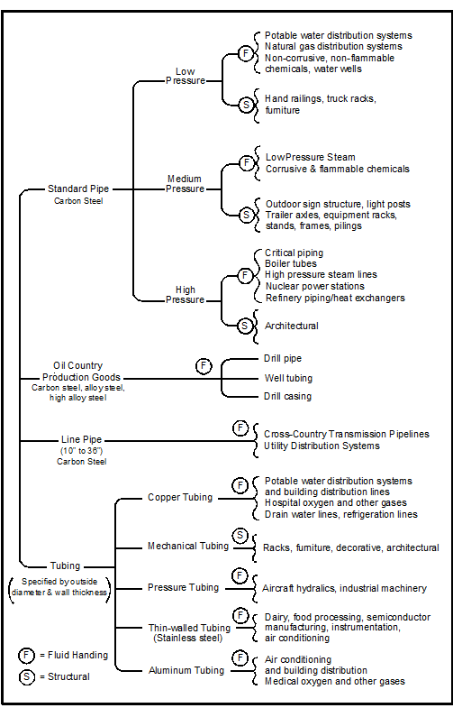
Figure 16-2 outlines an overview of the common types of pipe and tubing by application and by name. The F beside an application means that the pipe or tubing is for fluid handling and the S means it is for structural applications.

Figure 16-2. Common types of pipe and tubing and their uses.

