- Preface
- Acknowledgements
- Chapter 1: Welding Overview
- Chapter 2: Safety
- Chapter 3: Terms, Joints, & Edge Preparation
- Chapter 4: Tools & Welding Tables
- Chapter 5: Shielded Metal Arc Welding
- Chapter 6: Wire Feed Welding
- Chapter 7: Gas Tungsten Arc Welding
- Chapter 8: Oxyacetylene
- Chapter 9: Controlling Distortion
- Chapter 10: Cutting Processes
- Chapter 11: Brazing & Soldering
- Chapter 12: Common Problems & Solutions
- Chapter 13: Design Tips
- Chapter 14: Fabrication & Repair Tips
- Chapter 15: Tools & Tooling
- Chapter 16: Pipe & Tubing
- Chapter 17: Metallurgy
- Chapter 18: Power Supplies & Electrical Safety
- Chapter 19: Bending & Straightening
- Index
- Credits
Chapter 18
Power Supplies & Electrical Safety
Trouble is only opportunity in work clothes.
—Henry Kaiser
Introduction
All electrically-based welding processes require a power supply and the electrical characteristics of these power supplies need to match the requirements of each process. To help with this selection, this chapter covers power supply functions, output characteristics, power sources, designs and electrical safety.
Section I – Power Supply Functions
Welding power supplies have five functions:
- To convert input power from high voltage at low current to low voltage at high current. The voltage supplied by utility companies, usually 120–575 volts, is too high for welding processes that require voltages in the 20–80 volt range. Welding power supplies reduce utility voltage to within this required range and provide the ability to adjust the power supply’s output to the welding process. Trying to weld directly from a power line would cause excessive current to flow, blowing fuses and melting welding cables.
- To stabilize and regulate the arc with static voltage-vs.-current output characteristics of the power supply so they match the respective welding process. This means that the arc is maintained even when the arc length changes as the electrode-to-work distance or the electrode wire length fluctuates during welding. If using the wrong output characteristics, small changes in the electrode-to-work distance can extinguish or short out the arc.
- To adjust the dynamic—or transient—characteristics of the power supply to rapidly changing arc conditions since big changes in ionization of the arc column occur in as little as a millisecond.
- To convert 60 Hz AC to direct current, square waves, or to high frequency pulses to make a specific process possible or to improve its welding properties. In some cases, these waveforms are essential to performing the weld. Older power supply designs merely convert AC to DC, but under microprocessor control many modern power supplies can modify their output nearly instantaneously.
- To control shielding gas flow on GMAW, GTAW and plasma cutters and to control the wire-feed motor on GMAW and FCAW. Not only do power supplies control the solenoid gas valve, more sophisticated machines provide both pre-flow and post-flow shielding gas control as set on the machine. Many power supplies also turn on the torch cooling water by energizing an electric valve.
To simplify a complex subject, this chapter examines welding power supplies by dividing them three different ways:
- Input power sources – Internal combustion engines or electric utilities.
- Electrical output characteristics – Static and dynamic responses.
- Welding power supply designs – Engine driven generators and alternators, transformers, SCRs, and transistors.
Section II – Input Power Sources
Internal Combustion Engines
Gasoline or diesel engines drive DC generators or alternators. The simplest arrangement is to have an engine-driven DC generator for SMAW, traditionally the most popular field process. See in Table 18-1 on page 492.
With the increasing popularity of GMAW and FCAW, constant-voltage engine-driven welding power supplies to support both of these processes became available. See in Table 18-1.
Older designs for engine-driven welding power supplies did not contain semiconductors, but modern ones do. Adding semiconductor diodes to an alternator provides both AC and DC outputs. For field use, these engine-driven generators are the only choice and are widely used in construction, cross-country pipelining and oil refinery operations.
Progressing from light to heavy duty service, the engines used are: air-cooled gasoline engines, water-cooled gasoline engines, and diesel engines.
Alternators
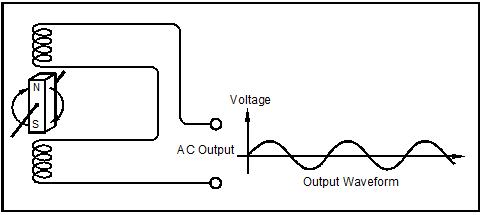
Alternators, or AC generators, similar to those in autos, contain a set of coils, called windings. When the magnetic field cutting through the windings fluctuates as the generator shaft is turned, it induces a voltage in the windings.
Since the field passes through a maximum strength in one direction, through zero strength, and then a maximum strength in the reverse direction, an alternating current is generated. Whether the coil is fixed and the magnetic field rotates, or the magnetic field is fixed and the coil rotates between the magnet’s poles, the result is the same: AC voltage appears at the generator’s output. See the simplified alternator in Figure 18-1. Practical AC generators have more windings and turns of wire in each winding than pictured in this figure.

Figure 18-1. Simplified alternator with its output waveform.
DC Generators
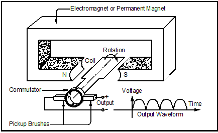
In order for a generator to produce DC—which is often more desirable than AC for welding—a rotating mechanical switch called a commutator is needed so that the voltage and current flow in the same direction even though the magnetic field through the generator coils reverses as the rotor turns. A series of copper bars connected to each generator rotor coil contacts a set of carbon, or graphite, conductive brushes. The commutator connects the coil to the brushes only when the coil is in the proper location to keep current flowing in the same direction. The idea is that adding a commutator to the basic alternator makes it a DC generator.
Figure 18-2 shows a DC generator and its simplified commutator. Practical DC generators have 20–50 coils with many turns of wire on each coil. For each coil there is a pair of commutator bars, but the principle remains the same. Also, there are usually some additional means of regulating the generator to stabilize its output with changing loads.

Figure 18-2. Simplified DC generator and its output waveform. The direction of the generator coil rotation changes the polarity of the generator’s output.
Power Grid
The utility company supplies electrical power with two types of service:
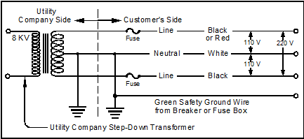
- Three-wire single-phase service is the most common means of supplying power to homes, offices and light industry. This hook-up provides both 110 and 220 volts. See Figure 18-3.

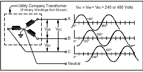
- Three-phase service is used by industry, especially industrial welding operations, typically 240 or 480 V phase-to-phase. See Figure 18-4.
Both the electric power company and the user enjoy benefits from this three-phase hook-up. In fact, the generators used at the powerhouse and at the electric power distribution system are themselves three-phase.
There are lower losses when transmitting three-phase power than with single-phase, both on the distribution system and within the user’s facility.
Here are two additional advantages to three-phase power:
- Motors run on three-phase power are more efficient than single-phase motors of the same size on single-phase power. Heavy loads on a single-phase system tend to unbalance the power distribution system, but heavy loads run on three-phase systems do not.
- Most important to welders, three-phase power converted to direct current is a much smoother, more even output with less ripple, which is better for welding. This will be covered later in the section called, Three-Phase Welding Machine Advantages, starting on page 495.

Figure 18-4. Three-phase power is used by industrial customers.
Power Factor
Power factor measures how much of the load is resistive and how much is inductive. A power factor of exactly one means that the load is purely resistive and has no charging currents for inductors—and their inductive losses. A power factor less than one indicates that the load has inductive currents. Power factor can be increased, or corrected, by adding capacitors inside the welding machine.
Because power companies penalize industrial customers with low power factors, the power factor of a welding power supply is important economically. To the power company a welding transformer load “looks” like both a resistive and an inductive load. Although inductors do not consume power themselves, the power company must supply the current they use and return on each cycle. Watt-hour meters do not measure this charging current. This current, though, does consume energy as it goes to and from the power plant through the power distribution network to the customer’s inductive load each half AC cycle. In effect, the power company is supplying a charging current at no cost and must pay for the heat losses incurred in its transmission.

