- Title Page
- Copyright Page
- Contents
- Preface
- Acknowledgements
- Chapter 1: Setting Up Shop
- Chapter 2: Metals, Alloys, Oils & Hardness Testing
- Chapter 3: Tapers, Dowel Pins, Fasteners & Key Concepts
- Chapter 4: Filing & Grinding
- Chapter 5: Drilling, Reaming & Tapping
- Chapter 6: Bandsaws
- Chapter 7: Lathes
- Chapter 8: Milling Machines
- Chapter 9: Machine Shop Know How
- Index
- Credits
Chapter 3
Tapers, Dowel Pins,Fasteners & Key Concepts
The greatest unexplored territory in the world is the space between the ears.
—Bill O’Brien
Introduction
This chapter covers a variety of subjects critical to understanding machine shop work: Morse tapers and their repair, 5C and R8 collet dimensions, threaded fasteners, and clearcutting. These subjects may seem basic to some, but they are important concepts and a little review never hurts.
Section I – Tapers
Taper Functions
Most tapers position and hold a tool or workpiece precisely on an axis of rotation, often within a few ten-thousandths of an inch. Because their male-cone-within-a-female-cone design is self-centering, tapers line up on their axial position time after time without an alignment step. This simplifies changing set-ups.
Common Taper Designs
In the machine shop, there are five common taper designs:
- Morse tapers (MTs) are used in spindles and tailstocks of the majority of modern lathes. Tapers in spindles usually hold lathe centers, while tailstock tapers can hold not only lathe centers, but drill chuck arbors and large twist drills. Tapers are also used to hold drill chuck arbors in drill press spindles. Many rotary tables have a Morse taper at their centers for holding center points or collets. The shallow taper of the MT cone makes them self-locking. This means that once seated by tapping them into place, MTs will hold in place without the need for a drawbar, but to release them, they must be tapped or pressed on their inside ends. Morse tapers come in eight sizes: 0, 1, 2, 3, 4, 5, 6 and 7. All sizes have slightly different tapers of about 0.62 inches/foot. There are two ways to identify the taper number of an unknown Morse taper. If the unknown MT is male, measure its taper in inches/inch as shown in Figure 3-1, and then find the matching taper in Table 3-1 (third column from the left). If the taper is female, measure its interior diameter at the end of the socket, and then find the matching diameter in Table 3-1 (far right column).
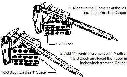
Figure 3-1. Measuring an unknown size Morse taper to determine its number.
|
MT Taper |
Taper |
Taper |
Diameter at |
|
0 |
0.62460 |
0.05205 |
0.3561 |
|
1 |
0.59858 |
0.04988 |
0.475 |
|
2 |
0.59941 |
0.04995 |
0.700 |
|
3 |
0.60235 |
0.05019 |
0.938 |
|
4 |
0.62326 |
0.05193 |
1.231 |
|
5 |
0.63151 |
0.05262 |
1.748 |
|
6 |
0.62565 |
0.05213 |
2.494 |
|
7 |
0.62400 |
0.05200 |
3.270 |
Table 3-1. Morse taper dimensions.
Morse tapers come in three variations:
- Without tang – This includes most live and dead lathe centers. See Figure 3-2 (top).
- With slits and drawbar threads – These are collets. See Figure 3-2 (middle).
- With tang – These are for MT shank drills to prevent them from spinning. See Figure 3-2 (bottom).
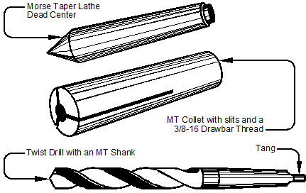
Figure 3-2. The three Morse taper designs. The extended shank on the twist drill prevents the drill from spinning under load and makes it easy to eject from the lathe spindle.
Many older lathes used MT collets directly in their spindles, and Sherline lathes still do. But today, most larger lathes with MT spindle holes have a reducing adapter to hold smaller MTs. For example, the Kent 13340 lathe has an MT 5-sized spindle hole, but with its spindle MT adapter installed, it can hold an MT 3. Besides the cost savings, this is a great advantage as the tailstock also takes the same size center. Another tool today that uses MTs is the rotary table, which has a female MT center hole to accommodate a collet for holding work or center points.
- Jacobs tapers (JTs) are confined to drill chucks and their arbors. There are nine JT sizes: 0, 1, 2, 2 short, 3, 4, 5, 6 and 33. The 33 is not a typo; it’s an odd numbering system. See Table 3-2. Like Morse tapers, JTs are self-locking, but because drill chucks, once placed on their arbors, are infrequently changed, considerable force is needed to secure them so that the chuck and its taper do not come apart under load. See Figure 3-3.
|
JT Taper Number |
Taper |
Small End |
Big End |
Length |
|
0 |
0.59145 |
0.22844 |
0.2500 |
0.43750 |
|
1 |
0.92508 |
0.33341 |
0.3840 |
0.62625 |
|
2 |
0.97861 |
0.48764 |
0.5590 |
0.87500 |
|
2 Short |
0.97861 |
0.48764 |
0.5488 |
0.7500 |
|
3 |
0.63898 |
0.74610 |
0.8110 |
1.21875 |
|
4 |
0.62886 |
1.0372 |
1.1240 |
1.6563 |
|
5 |
0.62010 |
1.3161 |
1.4130 |
1.8750 |
|
6 |
0.62292 |
0.6241 |
0.6760 |
1.0000 |
|
33 |
0.76194 |
0.5605 |
0.6240 |
1.0000 |
Table 3-2. Jacobs taper dimensions.
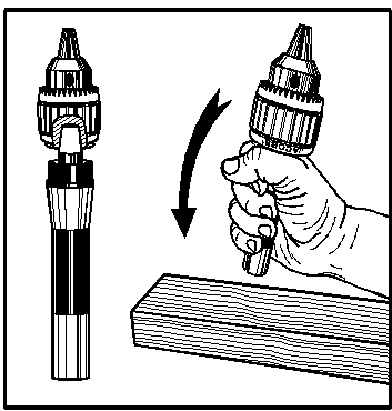
Figure 3-3. JTs are secured by placing the male and female tapers together and striking the opposite end of the arbor on a piece of wood. The inertia of the drill chuck produces large forces when the arbor stops suddenly upon striking the wood and forces the chuck onto the arbor. Do not use an arbor press.
- 5C collets are the most common collet design, although there are dozens of others. 5C collets are used in medium-sized lathes, indexing heads and in collet blocks. See Figure 3-4 for 5C collet dimensions.
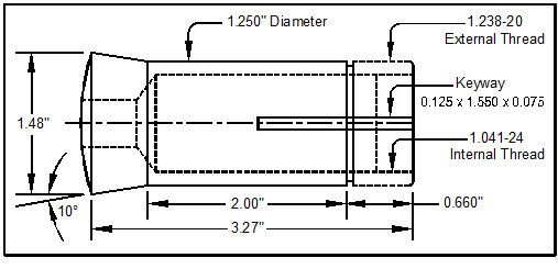
Figure 3-4. 5C collets are the most common of the dozens of collet designs.
- R8 collets are widely used on Bridgeport-style milling machines to hold tools in their spindles. See Figure 3-5 for R8 collet dimensions.
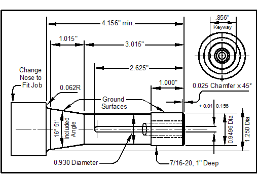
Figure 3-5. R8 collets are the most common Bridgeport-style milling machine collet.

