- Title Page
- Copyright Page
- Contents
- Preface
- Acknowledgements
- Chapter 1: Setting Up Shop
- Chapter 2: Metals, Alloys, Oils & Hardness Testing
- Chapter 3: Tapers, Dowel Pins, Fasteners & Key Concepts
- Chapter 4: Filing & Grinding
- Chapter 5: Drilling, Reaming & Tapping
- Chapter 6: Bandsaws
- Chapter 7: Lathes
- Chapter 8: Milling Machines
- Chapter 9: Machine Shop Know How
- Index
- Credits
Chapter 8
Milling Machines
Every discovery contains an irrational element of creative intuition.
—Karl Popper
Introduction
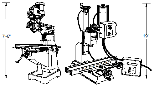
Milling machines are the second most important machine tool in the shop. The Bridgeport-style vertical milling machine, also called a turret mill or a knee-and-column mill, and its miniature cousin, the Sherline milling machine, are among the most popular. There are more Bridgeport-style mills in use than all other designs combined because of their easy set-up, flexibility and cost-effectiveness. Although there are several small table-top mills available today, the many accessories available for the Sherline make it a good selection for this study. These smaller machines, often called box mills, lack the moveable quill of a full-sized Bridgeport, but they are an excellent choice for smaller work, smaller workshops and smaller budgets. See Figure 8-1.

Figure 8-1. Bridgeport Series I Standard Milling Machine (left)
and Sherline Miniature Mill with DRO (right).
Lathes and mills are complementary machines. While lathes rotate the workpiece and produce a cylindrical cut, milling machines move work into a rotating cutter and make a straight-line cut. Lathes and mills are both capable of boring large-diameter holes, but mills are better at placing holes anywhere on the surface of the work. Although you can sometimes make do with just a lathe or a mill, a well-equipped shop needs both machines.
Milling Machine Evolution
Milling machines developed from rotary files, circular cutters with small file-like teeth that run in a lathe headstock. Rotary files date from the 1760s and were developed to reduce the time and effort of hand filing.
The early 1800s saw the first true milling machines. These machines used toothed rotary cutters turning on a horizontal axis and had table movement on the two horizontal axes, now called the x- and y-axes. A drawback of these early milling machines was that they had no provision for vertical table movement and so the work had to be shimmed up to meet the cutter.
In the mid-1800s, John R. Brown of Brown and Sharp, introduced the universal milling machine. This was a distinct improvement because its milling table swiveled around the vertical axis and had vertical table movement. A swiveling table allowed the cutting of helices with the table leadscrew geared to an indexing head, a giant step forward in cutting tool, drill and gear manufacturing. Also, the vertical table movement made for faster set-ups.
The early years of the 20th century ushered in more innovation in the form of anti-backlash leadscrew nuts that permitted coordinate positioning to 0.001 inches or better from a single reference point. This important development allowed parts to be made directly from prints rather than from jigs. By the 1930s, hydraulic tracer milling machines could make multiple parts by copying from a template. These two developments, coördinate positioning and pattern tracing, laid the groundwork for CNC machining, which began in the 1950s. The further refinement of horizontal milling machines led to the near extinction of shapers and planers since most of their work is now better done on a milling machine.
The Bridgeport Design
Another important development came in the 1930s when Rudolph Bannow and Magnus Wahlstrom brought out the Bridgeport vertical milling machine. Though traditional horizontal milling machines have higher metal removal rates, the Bridgeport design offers quicker set-up time, economy and versatility. Because of this versatility, there are more Bridgeport-style mills in existence today than any other milling machine design. Traditional horizontal mills are now usually reserved for production applications where high metal removal rates on identical parts are needed, not for prototypes and short runs.
The Bridgeport-style vertical machine offers many advantages over older horizontal milling machine designs:
- The biggest advantage is the quill’s ability to advance and retract the cutter easily without cranking to raise and lower the milling table. This speeds production and reduces operator fatigue. The retractable quill lets the machinist quickly withdraw the tool to clear chips from a hole or to check its progress. Also, tactile feedback through the quill feed handle or handwheel tells the machinist how the tool is cutting and lets him optimize the feed rate with less danger of tool breakage. Vertical table movement is still available for high-accuracy depth adjustment or when more axial force on the tool is required.
- The second largest advantage is the Bridgeport’s ability to make angle cuts. With the horizontal milling machine, either the milling cutter is made on an angle or the work must be positioned at an angle to the spindle axis. With the Bridgeport machine the operator merely needs to tilt the spindle to make an angle cut. Of course, with the Bridgeport you can also use an angled cutter or mount the work on an angle.
- Vertical milling machines must use smaller cutting tools than horizontal mills because they have smaller, less rigid castings and lower horsepower motors. Still, vertical milling machines can accomplish the same end results as horizontal mills, just more slowly. Bridgeport-style milling machines usually have 1–5-hp motors and smaller castings than most horizontal mills, which often have 20–50-hp motors. Because of this, Bridgeports generally cost less.
- Vertical milling machines—with their gearing located inside the head—are less complex than horizontal machines because the one-piece head eliminates the complicated gearing of horizontal milling machines.
- Bridgeport-style mills provide better visibility of the end mill cutter.
In the last two decades, digital readouts (DROs) and CNC controls have been added to Bridgeport-style mills. With their additional capabilities, these machines can now engrave—drive the tool to cut numbers and letters in various sizes and fonts—cut radii and angles without a rotary table, make islands, pockets, and cut ellipses and frames. Entering the position, diameter and number of holes automates cutting a bolt-hole pattern; the system does the math. The computer can also automatically compensate for the reduced diameter of resharpened milling cutters, saving time and money, and improving accuracy. In addition, the computer control systems can be manually programmed through their control panels, use stored programs, “learn” new tasks by memorizing a series of manual operations as the operator makes the first part, or accept files from CAD programs.
Section I – Milling Machine Design
Castings
A Bridgeport-style milling machine has nearly a dozen iron castings. Over time the dimensional stability of these castings is critical for machine accuracy. Because several of these castings are quite large, during production the outermost cast metal cools more rapidly than the internal metal, setting up internal stresses. These residual stresses gradually even out with time, but warp the castings in the process. This is why castings cannot be machined too soon after they are poured or bad things will happen.
The traditional method used to eliminate residual stress was to pour the castings, let them age outdoors in the weather for a year, then machine them. Bridgeport, as well as Rolls Royce, followed this practice. Twelve months of natural temperature cycling gave the cast iron a chance to work out its internal stresses and become dimensionally stable. Today, many quality machine builders use Meehanite castings, which are made according to a licensed process. By adding proprietary materials to the molten cast iron, solidification occurs with fewer internal stresses. These castings are dimensionally stable and ready to machine immediately. Machines made with the Meehanite process carry the logo in Figure 8-2 on the top front of the base casting. Poorer quality machines which do not use this process may experience dimensional changes in the first year or so of their lives.

Figure 8-2. The Meehanite logo is found on quality machine tool castings.
When comparing different mills, always consider their weight. Milling puts large forces on machine castings, which can deflect the cutting tool out of alignment. When machine builders put more cast iron into their machines, rigidity and accuracy usually improve. One rough way to check a mill’s rigidity is to place a DTI on the milling table with the DTI’s foot against the spindle, then lean against the table or head and observe the indicator’s deflection. It should not deflect more than a fraction of one-thousandth of an inch. Smaller Bridgeport-style mills weigh in at 1650 lbs, larger manually-operated versions at 2800 lbs, and the CNC-equipped mills at nearly 4000 lbs. Heavier machines, because of their larger and more rigid castings, can use larger horsepower motors and can take larger cuts before chatter begins. Also, these machines can take large accurate cuts because of their rigid frames.
Table Size
Although a few of the small Bridgeport-style mills have 8336-inch tables—that is, 8-inches wide and 36-inches long—full-size Bridgeport-style mills begin at 9349 inches and go up to 10350. Many CNC versions are 12350.
Horsepower
Motor horsepower has gradually increased over the years with the evolution of the Bridgeport-style mill. Early mills had ¼-hp motors, very small when you consider that a home vacuum cleaner has about 2 hp. Later mills went to 1 hp, then 2 hp, and today are mostly 3 and 5 hp. Eventually, even a low-power mill will get the job done, but a more powerful machine will get the job done quicker.
Spindle Speed Control
Early Bridgeport-style mills had belts and pulleys that produced eight spindle speeds—four in direct drive and four in backgear. To change spindle speed with this arrangement, the mill had to be stopped and the drive belt shifted from one pulley to another.
The next mill improvement, variable-speed heads, changed the spindle speed by using variable width pulleys. These pulleys have V-grooved sheaves in which the groove width can be mechanically increased or decreased, allowing the belt to ride in the groove at various diameters, effectively changing the pulley diameter—and the spindle speed.
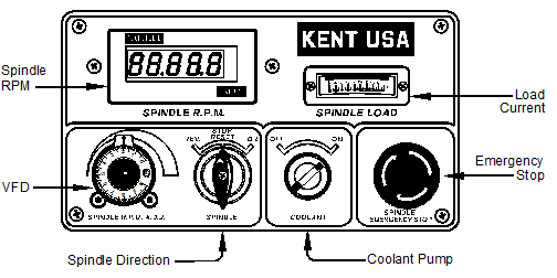
The latest mill improvement is the variable frequency drive (VFD). VFDs are small—a 3-hp unit is the size of a shoebox—and their cost continues to decline. Many machinists who use older three-phase machines can set their drive belts to medium speed, attach a VFD, and enjoy the benefits of this time-saving technology. See Figure 8-3.
VFDs have many advantages:
- Variable frequency drives eliminate the confusing practice of running the spindle motor backward to get the spindle to turn forward when in backgear, as with the traditional Bridgeport-style design. With VFDs, forward is forward and backward is backward in direct drive or in backgear.

Figure 8-3. A Kent milling machine power panel.

