- Title Page
- Copyright Page
- Contents
- Preface
- Acknowledgements
- Chapter 1: Setting Up Shop
- Chapter 2: Metals, Alloys, Oils & Hardness Testing
- Chapter 3: Tapers, Dowel Pins, Fasteners & Key Concepts
- Chapter 4: Filing & Grinding
- Chapter 5: Drilling, Reaming & Tapping
- Chapter 6: Bandsaws
- Chapter 7: Lathes
- Chapter 8: Milling Machines
- Chapter 9: Machine Shop Know How
- Index
- Credits
Chapter 7
Lathes
All great ideas are rejected by ‘experts.’
Anon.
Section I – Lathe Design
Lathe Operations
Lathes are the most versatile of all machine tools; they can face, turn, chamfer, neck, taper, drill, bore, ream, spin, file, polish, hone, buff, knurl, cut internal and external threads and cut off work. No other machine tool performs as many operations.
Lathe Construction
- Castings – Most lathes use iron castings as their basic structure. Besides providing a rough shape on which to begin machining, castings hold all the other lathe components in position and dampen tool vibrations. Both rigidity and damping affect accuracy, maximum cut depth and chatter tendency. In general, with two lathes of the same swing and bed length dimensions, the one with the larger castings—and greater weight—will perform better, allowing larger cuts before the tendency to chatter. When evaluating a lathe, check its net weight. Heavier is usually better.
- Pedestals vs. Cabinets – There are many medium-sized lathes of the same dimensions available in both bench-top and pedestal designs. In most cases, pedestal designs are superior because they weigh more and are more rigid. If the pedestals are castings rather than sheet metal cabinets, they will definitely perform better.
- Motor Integration – Many smaller lathes have motors which are integral to their castings. That is, the lathe casting actually holds the motor bearings, making it necessary to obtain an exact duplicate motor for a replacement. A much better approach is to have a lathe designed so that when its motor burns out, or the AC power requirements change, the motor can be easily replaced with a standard motor.
- Gap-Bed Lathes – With this type of lathe, a section of the lathe bed at the spindle end is removable, as in Figure 7-1. When this bed section is removed, short workpieces with large diameters can be machined. For example, when a 9-inch bed section of a 13340-inch lathe is removed, work as large as 18-inches diameter may be turned. However, there is only about 6½ inches of additional bed freed up because the D1-4 chuck mount extends over the bed. Because of this, work is usually held on faceplates when the gap is removed to provide the maximum usable gap length.
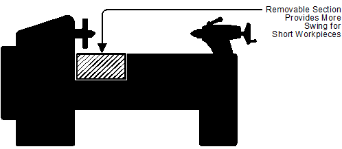
Figure 7-1. Gap-bed lathes provide additional swing, but only for short workpieces.
Though handy at times, the removable gap section is easily damaged when it has been removed from the lathe and may be troublesome to re-install accurately.
This removable section is secured by several SHCSs and one or more taper or dowel pins at the factory before the lathe bed is machined. Then the entire lathe bed is machined as if it were one piece. While a removable gap provides more machining capability, re-installing the gap is tricky and may not always come out well. If you do not really need this extra swing, do not remove the gap. Inflicting even the slightest damage on the gap-bed section when it is removed will prevent a perfect re-installation.
Lathe Drives
There are many different ways that electric motors connect to lathe spindles. Here are some of the main designs:
- A single-belt drive with a pair of step pulleys, shown in Figures 7-2 and 7-3, is the most basic design. Jewelers’ lathes, Sherline lathes, and small instrument lathes use a single round rubber, leather or plastic drive belt between two step pulleys. This arrangement provides a range of speeds. Some older jewelers’ lathes have foot-pedal speed controls like sewing machines. The drive belt also serves as a protective link by slipping and acting as a mechanical fuse should the lathe become overloaded or stalled. Since the diameter of work in these lathes is small, a single pair of step pulleys provides a range of speeds matching the needed work SFM. This is a valuable feature. Older jewelers’ lathes use AC–DC motors running on AC, sometimes called universal motors, but more recently, permanent magnet DC motors with an SCR speed control are used. The Sherline lathe in Figure 7-3 has a 70–2800 rpm speed range, while Levin lathes have a range of 0–5000 RPM. Traditional jewelers’ lathes run from several hundred to 4000 RPM in 4 or 5 fixed steps.
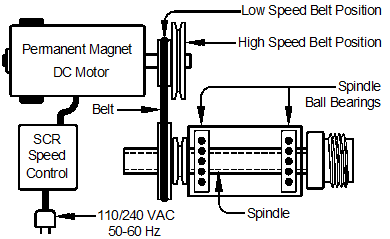
Figure 7-2. Schematic of a single-belt drive with step pulleys typical of jewelers’
lathes, Sherline lathes and imported mini-lathes.
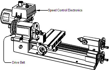
Figure 7-3. A single-belt drive—also called a direct drive—with a pair of step
pulleys on the lathe is typical of small instrument and jewelers’ lathes.
- A countershaft with two pairs of step pulleys, as in Figures 7-4, provides both greater speed reduction and more speed increments than a single-belt drive. Single-phase 60 Hz induction motors on these lathes have a fixed speed of 1750 RPM, so more speed reduction is needed than on smaller lathes. This drive design is standard on Atlas, Myford, South Bend, Logan, Clausing and many other lathes with swings of 5–15 inches. Older lathes have flat leather belts, while newer ones use one or more V-belts.
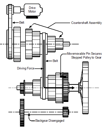
Figure 7-4. Countershaft with two step pulleys and a backgear for
small- and medium-sized lathes; backgear disengaged.
This lathe design has a backgear, a clever arrangement of gears which, in addition to the speed reduction provided by the countershaft, provides low spindle speeds—25–50 —and high torque. This enables the lathe to turn large diameter work without stalling. Low spindle speeds are also useful when cutting threads which run up to a shoulder because a slow spindle speed gives the operator time to stop the carriage before running the tool into the shoulder. For the higher speed range, the backgear is disengaged and a movable steel pin on the bull gear is pushed to the left. This locks the bull gear to the spindle, making the spindle turn at the same speed as the drive pulley. Figure 7-4 shows the backgear disengaged, which makes the spindle-drive belt and the spindle turn at the same speed. This is what provides the higher speed range.
When the moveable steel pin on the bull gear is pushed to the right, the pin remains inside the bull gear, and the bull gear turns independently on the spindle shaft. When the backgears are swung into position, as in Figure 7-5, the backgear is engaged and torque feeds through them, producing a lower spindle speed, but more torque.
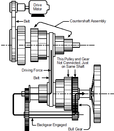
Figure 7-5. Countershaft with two step pulleys and a backgear for
small- and medium-sized lathes; backgear is engaged.
To engage or disengage the backgear, the lathe operator must stop the machine, open the headstock cover, move the bull gear pin and change the backgear position. Belts may also have to be repositioned.
- Belt and pulleys driving a geared transmission, similar to those of a car, provide a range of spindle speeds for larger lathes. See Figure 7-6. Lathes with swings of 15 inches and over used this design until the introduction of variable-frequency drive lathes. These larger belt-and-pulley lathes have two or three V-belts from the motor to the transmission. Several levers on the face of the headstock shift the transmission gears for different speeds. There is no need to open the headstock lid to change gears. The available speeds are in fixed increments, ranging from 35 to 1500 rpm.
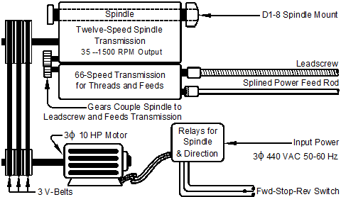
Figure 7-6. Belt-drive geared transmission for larger lathes.
- A variable-frequency drive (VFD) controls the speed of a three-phase induction motor which drives a geared transmission through V-belts. See Figure 7-7. This arrangement offers several advantages:
- The two-speed transmission for these machines is much less complicated than the older style lathe transmission because it has only a low speed range (85–500 rpm) and a high speed range (500–3000 RPM). The rest of the speed adjustment is done with a speed-control knob.
- A VFD provides infinitely variable speeds at the turn of a knob and the optimum spindle speed can be adjusted without shifting belts or gears.
- The VFD electronics provides a gradual “soft start” and a smooth, rapid electronic braking action to the spindle when the motor is shut off. There is no need to use the mechanical brake or wait for the spindle to coast to a stop. Both starting and stopping rates are programmable.
- The VFD electronics permits these drives to operate on either single-phase or three-phase input power. This is a very big advantage to a home shop because three-phase power is generally not available to a residence, yet larger lathe motors require it.

